Tie Wire Is Not Structural, but Slab Top Bars Still Need Ties and Spacers
"Tie wire is not structural." I hear it on many sites, and it is true. No code counts tie wire for strength, bond or lap length.
But sometimes the idea goes one step further: if it is not structural, it does not matter. Crossings are left untied, spacers under the top bars are few, and during the pour the top bars get pushed down. Here is why that matters, with a sample slab panel checked to NSCP 2015.
What tie wire and spacers are for
Tie wire (usually #16 GI wire, about 1.6 mm) holds the bars in place during the pour. Spacers hold them at the right height. That job is in the code. NSCP 2015 Section 426.6.2.2(a) requires reinforcement to be placed within tolerance and supported so that it does not move out of tolerance during concrete placement. The ACI 318 commentary (R26.6.2.2(a)) names the causes: concrete placement and workers.
Why the top bars over the beam matter most
In the middle of a panel the slab sags and the bottom bars take the tension. Over an interior beam, where the slab continues, it bends the other way: the top is in tension, carried only by the top bars.
Their strength depends on d, the distance from the compression face to the centre of the tension bars. Over the beam that face is the bottom of the slab, so d is measured from the soffit up to the top bars. The bar force times the lever arm (d − a/2, where a is the depth of the compression block) gives the moment strength. Push the bars down and the lever arm shrinks.
The top bars are also the easiest to push down, because the crew crosses them while pouring (buhos). This is not about any one trade; people have to stand somewhere. The fix is in how the bars are supported.
The sample panel
I ran the sample panel of our Two-Way Slab Designer several times, changing only the top-bar position:
- S-1, second floor of a two-storey residence, corner panel (one long and one short edge continuous)
- Clear spans 3.8 × 5.0 m, slab 125 mm, interior (20 mm clear cover)
- f'c = 21 MPa, fy = 420 MPa, superimposed dead load 1.5 kPa, live load 2.0 kPa (sample inputs, not code values)
- All bars 10 mm @ 200 mm
Self-weight is 24 kN/m³ × 0.125 m = 3.0 kPa, so wu = 1.2 × (3.0 + 1.5) + 1.6 × 2.0 = 8.6 kPa (NSCP 405.3.1). The moments come from the ACI 318-63 Method 3 coefficient tables, an analysis NSCP 2015 408.2.1 permits. At m = 3.8 / 5.0 = 0.76, the corner-panel table gives Ca,neg = 0.075 (0.076 at m = 0.75, 0.071 at 0.80). With la = 3.8 m, the short clear span, the moment at the continuous edge (short direction, middle strip) is
Mu− = Ca,neg · wu · la² = 0.075 × 8.6 × 3.8² = 9.31 kN·m/m
The short-direction top bars are the outer layer, with centres 20 + 5 = 25 mm below the top, so d = 125 − 25 = 100 mm. As designed, φMn = 14.16 kN·m/m and the ratio Mu/φMn is 0.66 (1.00 or less passes): SLAB ADEQUATE.
To model the drop, I raised the cover input and read only the top-bar rows.
Case A: too few spacers, bars not tied, pushed down 40 mm
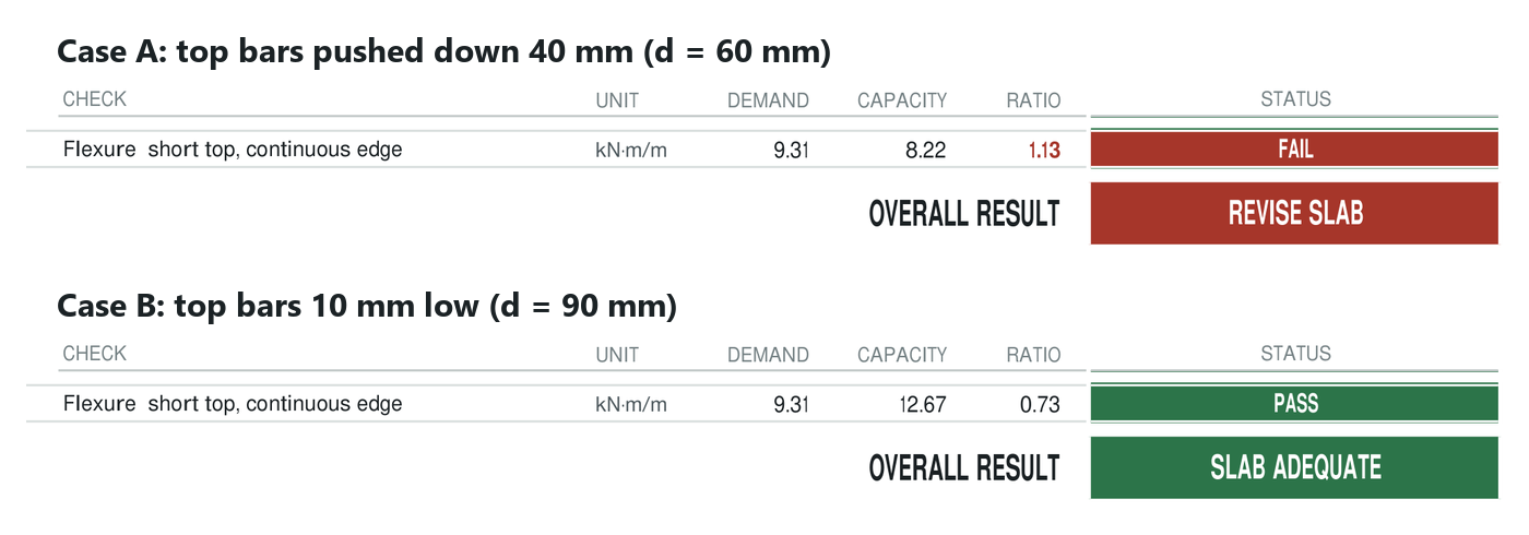
Suppose the top bars are stepped on (naapakan) and pushed down 40 mm at the beam face, to about mid-depth (an assumed drop). d falls from 100 to 60 mm.
| Check (short top bars at the beam) | Needed | Case A | Result |
|---|---|---|---|
| Bar position, d (NSCP Table 426.6.2.1(a)) | at least 90 mm (−10 mm) | 60 mm | Out of tolerance |
| Moment strength φMn ≥ Mu− | 9.31 kN·m/m | 8.22 kN·m/m | FAIL, ratio 1.13 |
Overall: REVISE SLAB. It is the only row the sheet flags. The strength fell from 14.16 to 8.22 kN·m/m: 8.22 / 14.16 = 0.58, about 42% less, with the same steel.
FAIL means the design check is not met: the design strength is below the moment the code requires, with its load factors and φ. It does not mean collapse. It means the code's safety margin is gone. Only the engineer of record can judge an as-built slab.
Case B: tied tight and on spacers
NSCP 2015 Table 426.6.2.1(a) allows ±10 mm on d where d is 200 mm or less. I checked the worst case, 10 mm low (d = 90 mm).
| Check | Needed | Case B (10 mm low) | Result |
|---|---|---|---|
| Bar position, d | at least 90 mm (−10 mm) | 90 mm | Within tolerance |
| Moment strength φMn ≥ Mu− | 9.31 kN·m/m | 12.67 kN·m/m | PASS, ratio 0.73 |
Overall: SLAB ADEQUATE. This panel passes because it was designed with margin. With less margin, the engineer may specify a tighter tolerance; follow the plans' general notes.
Hand check
For a strip b = 1,000 mm wide, with one 10 mm bar = 78.54 mm²:
φMn = φ · As · fy · (d − a/2), with a = As · fy / (0.85 · f'c · b)
- As = 1,000 × 78.54 / 200 = 392.7 mm²/m
- a = 392.7 × 420 / (0.85 × 21 × 1,000) = 9.24 mm, so a/2 = 4.62 mm
- φ · As · fy = 0.90 × 392.7 × 420 = 148,441 N per metre width
- d = 100: 148,441 × 95.38 / 10⁶ = 14.16 kN·m/m; d = 90: 148,441 × 85.38 / 10⁶ = 12.67; d = 60: 148,441 × 55.38 / 10⁶ = 8.22
At d = 60 the net tensile strain εt is 0.0136, above 0.005, so φ stays 0.90 (Table 421.2.2). The loss is purely the lever arm.
How far can the bars drop?
At 25 mm down the sheet gives 0.89 and at 30 mm 0.96, both passing; at 33 mm, 1.006: REVISE SLAB. By hand, with the unrounded Mu− = 9.314: the lever arm needed is 9.314 × 10⁶ / 148,441 = 62.74 mm, so d ≥ 62.74 + 4.62 = 67.36, about 67.4 mm. That is a drop of only 32.6 mm, about a quarter of the slab thickness.
With no spacers at all, the bars can end up flat on the bottom mat: d is about 45 mm, the ratio 1.55, and the long-direction top bars fail too (1.19).
The lesson
The drawing, the bars and the concrete can all be right, and the slab can still come out short, only because the top bars were in the wrong place when the concrete covered them. This sample has a fair margin (0.66, and 0.73 at the code tolerance), and a 33 mm drop uses all of it.
What to check before and during the pour
- Spacers (bar chairs) under the top bars on both sides of each beam, out to the bar ends on the plans: the right height, strong enough to stand on, tied in place, and close enough that a bar does not sag between them.
- Tie the top bars tight at the crossings, so the mat moves as one piece and stays on its spacers.
- Measure before the pour. From a string line at finished slab level down to the top bars, the cover should match the plans: 20 mm here. Too low loses d: at most 10 mm low. Too high loses cover: at most 10 mm or one-third of the cover, whichever is less (about 7 mm here).
- Give the crew a path. Lay planks over the top mat so nobody stands on the bars.
- Watch the bars during the pour. Have one person put any pushed-down top bar back on its spacers and re-tie it before the concrete reaches it. If it is already covered, stop and tell the engineer.
- Do not count tie wire as strength. Lap length comes from the code (development length and lap splices), not from tight tying. In beams and slabs, lapped bars may even sit up to one-fifth of the required lap length or 150 mm apart, centre to centre, whichever is less (NSCP 425.5.1.3).
- If bars are out of place, put them back to the plan position before the pour. If you suspect afterwards that top bars were pushed down, or cracks appear along the top over the beams, tell the engineer of record. Do not judge it from this example.
General information only. Follow the approved structural plans and the engineer of record.