Strap Footing for a Column on the Property Line: Why an Ordinary Tie Beam Is Not Enough
On tight lots, the outer columns often stand on the property line, against the neighbour's fence. Their footings cannot be centred, or half would sit on the neighbour's lot.
So the footing is moved inward, with the column at its edge, and a tie beam is run to the next column to "hold" it. On a small drawing, that looks like a strap footing. But an ordinary tie beam is not automatically a strap. Here is why, with one real sample checked to NSCP 2015. (A combined footing is the other common answer.)
What happens when the column sits at the edge
A footing works best when the load is at its centre. Put the column at the edge and the footing wants to turn: the side under the column presses down hard, the far side lifts off, and the footing tilts (tumatagilid) toward the property line.
The test case
This is the shipped sample of our Strap Footing Designer (NSCP 2015), footing SF-1 of a warehouse:
- Column 1: 400 × 400 mm, PD 500 + PL 300 = 800 kN, centre 0.2 m from the property line
- Footing F1: 2.2 m along the strap × 3.2 m × 0.6 m, starting at the property line, base 1.5 m below ground
- Column 2 (interior): 450 × 450 mm, PD 900 + PL 600 = 1,500 kN, 5.0 m away, on a centred footing F2 of 3.2 × 3.2 × 0.7 m
- Soil: qa = 180 kPa, 18 kN/m³. Concrete 23.5 kN/m³, f'c = 28 MPa, fy = 420 MPa
First, the footing alone
The sheet always includes a strap, so I checked F1 alone by hand:
- Footing and soil on it: 2.2 × 3.2 × (0.6 × 23.5 + 0.9 × 18) = 213 kN, so N = 800 + 213 = 1,013 kN
- The column is 1.1 − 0.2 = 0.9 m from the footing centre: M = 800 × 0.9 = 720 kN·m
- Eccentricity of N: eN = 720 / 1,013 = 0.711 m, more than L/6 = 0.37 m, so part of the footing lifts off
- L/2 − eN = 1.1 − 0.711 = 0.389 m, so the contact length is 3 × 0.389 = 1.17 m of the 2.2 m
- q,max = 2N / [3B (L/2 − eN)] = 2 × 1,013 / (3 × 3.2 × 0.389) = 542 kPa
That is 3.0 times the 180 kPa allowed. In this sample, only about half the footing touches the soil, and that half is overloaded.
What a strap does
A strap is a stiff, heavy beam from the edge footing to the next interior footing. It does not rest on the soil. It works like a lever: column 1 pushes down at one end, column 2 holds the other end down, and the soil under F1 pushes up in between. Two effects are easy to miss.
1. The edge footing carries more than its column. Taking moments about column 2:
R1 = (P1 · s + Ws · s/2) / (s − e)
Here s = 5.0 m between the columns, e = 0.9 m is the distance from column 1 to the centre of F1, and Ws = 44.9 kN is the strap's weight (23.5 × 0.45 × 0.85 = 8.99 kN/m, times 5.0 m):
R1 = (800 × 5.0 + 44.9 × 2.5) / (5.0 − 0.9) = 4,112 / 4.1 = 1,003 kN
F1 is sized for 1,003 kN, not 800.
2. The strap bends with tension at the top. The soil pushes it up while both ends are held down, like a plank pushed up in the middle. So the main bars belong at the top.
Case A: an ordinary tie beam as the strap
Same footings and loads, with a tie beam 250 × 400 mm, 3-Ø16 top and bottom, 2-leg Ø10 stirrups @ 200 mm as the strap.
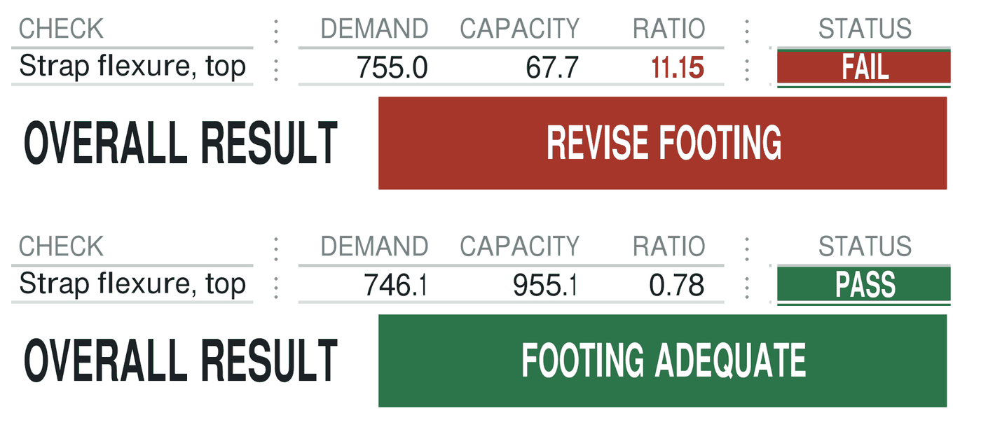
| Check (NSCP 2015) | Demand | Capacity | Result |
|---|---|---|---|
| Bending, top bars (φMn ≥ Mu−) | 755.0 kN·m | 67.7 kN·m | FAIL (ratio 11.1) |
| Shear at the face of column 1 | 839.4 kN | 132.4 kN | FAIL (ratio 6.3) |
| Stirrup spacing | 200 mm provided | 159 mm allowed (d/2) | FAIL |
Overall: REVISE FOOTING.
The sheet's required-steel line reads "too thin": more bars alone will not fix it. Bigger ties also failed in bending: 300 × 500 with 4-Ø20 top had a demand 4.2 times its capacity, and 350 × 600 with 4-Ø25 top 2.2 times.
The soil check under F1 still passes (139.6 kPa against 149.7) only because the sheet assumes the strap does its job. The strap lines say it cannot.
Case B: the sample strap (gravity loads)
The sheet's own sample, unchanged: strap 450 × 850 mm, top 6-Ø28, bottom 4-Ø20, 4-leg Ø12 stirrups @ 150 mm.
| Check | Demand | Capacity | Result |
|---|---|---|---|
| Bending, top bars | 746.1 kN·m | 955.1 kN·m | PASS (0.78) |
| Shear at the face of column 1 | 836.1 kN | 948.2 kN | PASS (0.88) |
| Top bars, straight anchorage at the property-line end | ld = 1,700 mm | 1,735 mm available | PASS (0.98), tight |
| Soil under F1 | 142.5 kPa | q,net 149.7 kPa | PASS (0.95) |
| F2 stays down with the live load off column 2 | R2 > 0 | 741.9 kN | PASS |
Overall: FOOTING ADEQUATE.
The anchorage row assumes 50 mm end cover. If that face is cast against earth (75 mm), the room is 1,710 mm: still enough, but only just. So I would hook the bars there.
A short hand check:
q,net = 180 − 23.5 × 0.6 − 18 × 0.9 = 149.7 kPa
q under F1 = 1,003 / (2.2 × 3.2) = 142.5 kPa ≤ 149.7, OK
For the strap, Pu1 = 1.2 × 500 + 1.6 × 300 = 1,080 kN (405.3.1). The same lever gives a factored soil force of 1,355.4 kN under F1, or 616.1 kN per metre of its 2.2 m. The strap weight is taken × 1.4 = 12.58 kN/m (the sheet's own conservative assumption; 1.2D + 1.6L would use 1.2). The largest moment, inside F1, is where the shear is zero, x0 = 1.785 m from the property line, which is 1.585 m from the centre of column 1:
Mu− = 1,080 × 1.585 + 12.58 × 1.585² / 2 − 616.1 × 1.785² / 2 ≈ 746 kN·m
For the top bars, a = 3,695 × 420 / (0.85 × 28 × 450) = 144.9 mm, so φMn = 0.9 × 3,695 × 420 × (756.3 − 144.9/2) ≈ 955 kN·m.
The lesson
In both cases the strap has to carry about 750 kN·m. The tie beam can carry 67.7. Two more things stand out:
- The main bars are at the top. The bottom moment is only 12.3 kN·m.
- Column 2's load holds the strap down, so the sheet checks it with the live load off (R2 = 741.9 kN, still down).
The method assumes a rigid strap, so the soil pressure under F1 stays even. Here the sheet flags the strap-to-footing stiffness ratio as a note for the engineer. A flexible strap lets F1 tilt and moves pressure toward the property line.
This is also a gravity-only check, with no column moments. In the Philippines the engineer of record must also check the strap and footings for the earthquake load combinations of NSCP 2015 Chapter 2, and for settlement.
What to check on site
- Before digging, check the neighbour's side (fence, wall, footing). A 1.5 m pit beside it may need shoring or underpinning, as the engineer of record directs. Do not leave it open long.
- F1 starts at the property line and does not cross it, with the column at its edge.
- The strap has the size on the plans (here 450 × 850), not a standard tie beam size.
- Main bars at the top, in the layers shown (here 4 + 2, with spacer bars between), hooked at the property-line end, with no laps near column 1 unless the plans allow.
- Closed stirrups with the legs and spacing on the plans (here 4 legs of 12 mm @ 150 mm).
- The strap does not bear on the soil. Leave the void or compressible fill under it as detailed.
- In F1, the main bottom bars run perpendicular to the strap (along the 3.2 m side): F1 bends as two cantilevers off it.
- If the site does not match the plans, stop and ask the engineer of record.
A note on blame
This is not about any one trade. On a small plan, a strap and a tie beam look the same: a line between two footings. A clear strap section on the plans fixes that.
General information only. Use the soil data from your own geotechnical investigation and follow the approved plans and the engineer of record.