More Steel, Less Design Strength: Net Tensile Strain and φ in NSCP 2015
When a beam comes out short, the usual reflex is to add bottom bars. On site, an extra bar is sometimes added just to be sure (para sigurado). More steel, stronger beam. Usually true.
But past a certain point, extra bottom bars can lower the beam's design strength and make it fail with less warning. Here is a sample beam checked to NSCP 2015.
What happens inside a beam in bending
In a simply supported beam, the concrete at the top is squeezed and the bottom bars are stretched. (In a frame, the same applies at the supports with the top bars in tension.)
Concrete is taken to crush at a strain of 0.003 (NSCP 422.2.2.1). How far the lowest layer of bars has stretched at that moment is the net tensile strain εt.
- Large εt: the steel yields well before the concrete crushes. The beam cracks, sags and warns. It is ductile.
- Small εt: the concrete crushes when the steel has barely yielded, or not at all. Little warning. It is brittle, over-reinforced in the code's sense.
Add bottom bars, and the bigger steel force needs a bigger concrete compression zone, so the neutral axis moves down. The bars end up closer to it and stretch less. More bottom steel, smaller εt.
How NSCP 2015 handles it
First, NSCP sets the strength reduction factor φ for bending (Table 421.2.2). With fy = 420 MPa and Es = 200,000 MPa, the yield strain is εy = 420 / 200,000 = 0.0021 (some books round it to 0.002).
| Net tensile strain εt | Section | φ |
|---|---|---|
| 0.005 or more | tension-controlled | 0.90 |
| between 0.0021 and 0.005 | transition | 0.65 + 0.25 (εt − 0.0021) / (0.005 − 0.0021) |
| 0.0021 or less | compression-controlled | 0.65 |
Second, for non-prestressed beams (Pu below 0.10 f'c Ag), it sets a floor: εt must be at least 0.004 (409.3.3.1).
So too much bottom steel lowers φ. Mn still rises, but φ can drop faster, and φMn can go down.
The test beam
I used the sample beam in our RC Beam Section Designer (NSCP 2015), B-1 of a two-storey residence:
- 350 × 500 mm, f'c = 28 MPa, fy = 420 MPa
- 40 mm clear cover, 10 mm stirrups, 6.0 m clear span, simply supported
- I set the factored moment to Mu = 350 kN·m and changed only the bars (and, for Case D, the depth).
Case A and Case B: adding two bars
Case A has 6-Ø25 (six 25 mm bars) at the bottom only. Case B adds two more: 8-Ø25, or 33% more steel. The sheet's four-bars-per-layer limit gives 4 + 2 and 4 + 4.
| Excel result | Case A: 6-Ø25 | Case B: 8-Ø25 |
|---|---|---|
| Steel area As | 2,945 mm² | 3,927 mm² |
| Neutral axis depth c | 174.7 mm | 232.9 mm |
| Net tensile strain εt | 0.0045 | 0.0026 |
| φ | 0.858 | 0.696 |
| Nominal strength Mn | 428.7 kN·m | 517.1 kN·m |
| Design strength φMn | 367.8 kN·m | 359.9 kN·m |
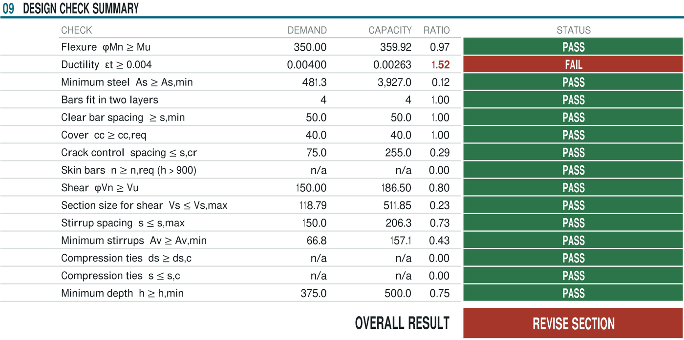
| Ductility, εt ≥ 0.004 | PASS | FAIL |
| Overall | SECTION ADEQUATE | REVISE SECTION |
Mn rose about 21%. But φ fell from 0.858 to 0.696, so the design strength fell from 367.8 to 359.9 kN·m. More steel, lower design strength, less warning.
Hand check of Case B
With β1 = 0.85 for f'c = 28 MPa (Table 422.2.2.4.3):
c = As · fy / (0.85 · f'c · β1 · b) = 3,927 × 420 / (0.85 × 28 × 0.85 × 350) = 232.9 mm
The lowest layer sits at dt = 500 − 40 − 10 − 25/2 = 437.5 mm. Then:
εt = 0.003 × (437.5 − 232.9) / 232.9 = 0.00263, below 0.004, FAIL
φ = 0.65 + 0.25 × (0.00263 − 0.0021) / (0.005 − 0.0021) = 0.696
a = 0.85 × 232.9 = 198.0 mm; d (centroid of both layers) = 412.5 mm
Mn = 3,927 × 420 × (412.5 − 198.0/2) / 10⁶ = 517.1 kN·m
φMn = 0.696 × 517.1 = 359.9 kN·m
Like the sheet, this assumes all eight bars yield. But the upper layer at 387.5 mm reaches only εs = 0.003 × (387.5 − 232.9) / 232.9 = 0.00199, below 0.0021. A layer-by-layer solve gives c = 230.2 mm and φMn = 360.3 kN·m: same conclusion.
When the concrete crushes, the lowest layer is at only 1.25 times the yield strain and the upper layer has not yielded. That is the brittle behaviour the 0.004 rule prevents.
The sheet's flexure line for Case B still says PASS (359.9 > 350); only the ductility line catches it. With φ taken as 0.90 by habit, φMn would be 0.90 × 517.1 = 465.4 kN·m, about 29% too high.
Case C and Case D: two fixes that work
| Excel result | Case C: 8-Ø25 bottom + 4-Ø20 top | Case D: 6-Ø25 bottom, h = 600 mm |
|---|---|---|
| εt | 0.0048 | 0.0062 |
| φ | 0.882 | 0.90 |
| Design strength φMn | 500.3 kN·m | 497.2 kN·m |
Case C: compression bars at the top. The four 20 mm top bars carry 455.7 kN of compression (net of the concrete they displace), so the concrete gives only 1,193.6 kN instead of 1,649.3 kN. So c = 168.6 mm, and εt = 0.003 × (437.5 − 168.6) / 168.6 = 0.0048.
Case D: a deeper beam. The same six bars, 100 mm deeper. c stays at 174.7 mm, but the bars are farther down: dt = 537.5 mm, so εt = 0.003 × (537.5 − 174.7) / 174.7 = 0.0062. Above 0.005, so φ = 0.90.
The sheet says SECTION ADEQUATE for both. Each gives about 500 kN·m, against 360 for Case B, and a beam that warns before it fails.
A note for frames. In a special moment frame, NSCP 418.6.3.1 also caps the steel ratio at 0.025. Cases B and C have ρ = 3,927 / (350 × 412.5) = 0.027 and would not pass; Case D, at 2,945 / (350 × 520.8) = 0.016, would. Extra beam bars also raise the earthquake shear on the beam, joint and columns.
The lesson
Adding bottom bars helps only while the concrete at the top can keep up. Past that, help the compression side or give the steel more depth.
This is not about any one trade. Adding a bar feels safe. But an over-reinforced beam looks stronger, and nothing on site shows that it is not.
What to check
- On site, do not add or upsize bars without the engineer of record's OK. Any change in the bars changes εt and, in a frame, the earthquake forces.
- In design, compute εt and φ for every beam. Check εt ≥ 0.004 (409.3.3.1), and aim for 0.005 or more so that φ = 0.90.
- If a beam needs more strength and εt is already low, add top compression bars or make the beam deeper, not more bottom bars.
- Treat designed top bars as real reinforcement, not just stirrup hangers, enclosed in the stirrups. Their tie spacing is limited to the least of 16 bar diameters, 48 tie diameters and the beam size (409.7.6.4.3): here 16 × 20 = 320 mm, against 150 mm provided. Frame beams need closer hoops at the ends.
- Watch the congestion. Eight 25 mm bars in a 350 mm beam already need two layers. Keep at least 25 mm clear between layers, with the upper bars directly above the lower ones (425.2.2), using short 25 mm bar spacers, and vibrate well.
General information only. Follow the approved structural plans, and refer any change in reinforcement to the engineer of record.