Isolated Footing Design to NSCP 2015: A Complete Worked Example
The isolated (spread) footing is the first thing most of us design on our own, and the one we design most often. It is also where small shortcuts hide: forgetting the moments, using gross instead of net soil pressure, or skipping the dowel check.
This article walks through one complete design, in the order an engineer should do it. Every number comes from a real run of our Isolated Footing Designer (NSCP 2015), so you can follow it with a calculator.
The footing
Footing F-1 of a two-storey residence:
| Input | Value |
|---|---|
| Column | 400 × 400 mm, 8 Ø 16 mm bars, f'c 21 MPa |
| Footing | 2.40 × 2.40 m, 600 mm thick, 75 mm cover (cast against ground) |
| Concrete / steel | f'c = 21 MPa, fy = 420 MPa |
| Soil | allowable bearing qa = 250 kPa, unit weight 18 kN/m³, base 1.50 m below ground, surcharge 5 kPa |
| Service loads | PD = 700 kN, PL = 350 kN |
| Service moments | MD = 15 (x), 10 (y) kN·m; ML = 10 (x), 5 (y) kN·m |
| Bottom bars | 15 Ø 16 mm @ 150 mm each way |
Step 1. Net allowable soil pressure
The 250 kPa from the geotechnical report is the pressure the soil can take in total. Part of it is already used by the footing's own weight, the soil on top of it, and the surcharge:
- Footing: 0.60 m × 24 kN/m³ = 14.4 kPa
- Soil above the footing: (1.50 − 0.60) m × 18 kN/m³ = 16.2 kPa
- Surcharge: 5.0 kPa
qnet = 250 − 14.4 − 16.2 − 5.0 = 214.4 kPa
Step 2. Size the footing with service loads
Service axial load Ps = 700 + 350 = 1,050 kN.
A,req = 1,050 / 214.4 = 4.897 m². Provided: 2.40 × 2.40 = 5.760 m². Ratio 0.85, OK.
But the column also carries moments. With them, the pressure is not uniform:
- Eccentricities: ex = 25 / 1,050 = 0.0238 m, ey = 15 / 1,050 = 0.0143 m
- Both are well inside the kern (L/6 = 0.40 m; combined ratio 0.095), so the whole base stays in compression.
- Section modulus S = 2.40³ / 6 = 2.304 m³
qavg = 1,050 / 5.760 = 182.3 kPa
qmax = 182.3 + 25 / 2.304 + 15 / 2.304 = 199.7 kPa ≤ 214.4 kPa, OK (ratio 0.93)
qmin = 164.9 kPa > 0, OK
The lesson: the area check alone counts only the axial load. Always check the corner pressure with the moments. If the soil were 220 kPa instead of 250, qnet would drop to 184.4 kPa. The area check would still pass (5.694 needed vs 5.760 provided), but qmax = 199.7 would be over 184.4 and the footing would fail. One line of the check catches it; skipping it does not.
Step 3. Factored loads
NSCP 2015 load combination 1.2D + 1.6L:
Pu = 1.2 × 700 + 1.6 × 350 = 1,400 kN
Mu,x = 1.2 × 15 + 1.6 × 10 = 34.0 kN·m; Mu,y = 1.2 × 10 + 1.6 × 5 = 20.0 kN·m
qu,avg = 1,400 / 5.760 = 243.1 kPa
The soil and footing weight are left out of the strength checks: they push down and up equally and cause no shear or bending in the footing.
Step 4. Effective depth
d (x) = 600 − 75 − 16/2 = 517 mm; d (y) = 517 − 16 = 501 mm (the second layer sits on top)
Average d for punching = 509 mm
Step 5. One-way (beam) shear
The critical section is at a distance d from the column face. φ = 0.75, and
φVc = 0.75 × 0.17 λ √f'c × b × d
| Direction | Vu | φVc | Ratio |
|---|---|---|---|
| x | 295.4 kN | 725.0 kN | 0.41 OK |
| y | 299.3 kN | 702.5 kN | 0.43 OK |
Step 6. Two-way (punching) shear
The critical perimeter is at d/2 from the column faces: each side = 400 + 509 = 909 mm, so
bo = 4 × 909 = 3,636 mm
For a square interior column, the governing stress is
φvc = 0.75 × 0.33 λ √f'c = 0.75 × 0.33 × √21 = 1.134 MPa
Punching stress (including the effect of the moments): vu = 0.684 MPa. Ratio 0.60, OK.
For footings, punching usually governs the thickness. If you are tempted to go thinner, check this first. In this example, at h = 450 mm punching fails (1.23 MPa against 1.134).
Step 7. Flexure
The cantilever from the column face to the edge is (2.40 − 0.40) / 2 = 1.00 m.
Mu (x) = 304.5 kN·m, Mu (y) = 299.2 kN·m (with the moment-induced pressure)
As,req (x) = 1,581.6 mm²
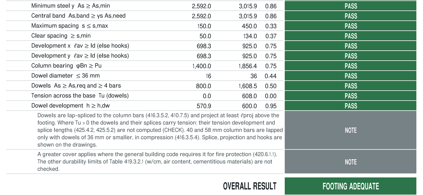
As,min = 0.0018 × b × h = 0.0018 × 2,400 × 600 = 2,592 mm² (governs)
Provided: 15 Ø 16 = 3,015.9 mm², OK
Capacity φMn = 572.5 kN·m (x) and 554.3 kN·m (y). The strain in the steel εt = 0.040, far above 0.005, so the section is tension-controlled and φ = 0.90 is correct.
Bar spacing: clear spacing 134 mm, maximum allowed 450 mm. OK.
Notice that the minimum steel governs, not the moment. That is normal for footings of this size; it is why a thicker footing does not automatically need more bars.
Step 8. Development of the bottom bars
The bars must develop their strength between the column face (where the moment is largest) and the end of the bar:
ld (Ø 16, NSCP 425.4.2) = 698.3 mm
Available = 1,000 − 75 (cover) = 925 mm. Ratio 0.75, OK, straight bars are enough.
If the footing were smaller, the bars might need hooks at the ends.
Step 9. Load transfer from column to footing
Bearing on the column base: φBn = 0.65 × 0.85 × 21 × 400 × 400 = 1,856.4 kN ≥ Pu = 1,400 kN, OK (ratio 0.75). No compression has to be carried by the dowels.
Dowels: NSCP 416.3 requires at least 0.005 × column area = 0.005 × 160,000 = 800 mm². Provided 8 Ø 16 = 1,608.5 mm², OK.
The dowels must also develop into the footing in compression. The footing must be deep enough for that: here the sheet needs h ≥ about 571 mm, and 600 mm is provided. At 550 mm this line would turn to "CHECK" (use hooks or a smaller bar).
Result
All 26 checks pass: FOOTING ADEQUATE.
| Check | Ratio |
|---|---|
| Soil pressure with moments | 0.93 |
| One-way shear (x / y) | 0.41 / 0.43 |
| Punching | 0.60 |
| Development of bottom bars | 0.75 |
| Bearing at the column | 0.75 |
| Dowels | 0.50 |
Five mistakes I see most
- Using qa instead of qnet for sizing.
- Checking the area with the axial load only and forgetting the moments.
- Using one d for both directions; the top layer has a smaller d.
- Forgetting As,min (0.0018bh) when the moment is small.
- Skipping the dowel and development checks, which often decide the minimum thickness.
General information only. Use the soil data from your own geotechnical investigation and follow the engineer of record.