Look at many column cages on residential sites and you will see the same tie: one square loop of 10 mm bar around the outside bars, hooks bent at 90 degrees, spaced at 200 mm from top to bottom. It is fast to bend and easy to tie.
For a column in a building that has to resist earthquakes, that detail is not enough. Here is why, with a real column checked to NSCP 2015.
What happens to a column in an earthquake
In a strong earthquake the ends of a column, just below and above the beams, are bent back and forth hard. The outer layer of concrete (the cover) cracks and falls off. That is expected; the design assumes it.
Once the cover is gone, the ties are the only thing holding the column together:
A 90-degree hook is anchored only in the cover. When the cover spalls, nothing holds the hook. It opens, the tie lets go, and the vertical bars buckle outward. The concrete core then crushes.
A 135-degree hook bends back into the core of the column. Even with the cover gone, it stays anchored in confined concrete and keeps holding.
That is why NSCP 2015 requires closed hoops with seismic hooks in special moment frame (SMRF) columns: a 135-degree bend with an extension of at least 6 bar diameters, but not less than 75 mm, into the core (Section 425.3 for the hook, 418.7.5.2 for the hoops).
Figure 1. 90-degree hook versus 135-degree seismic hook at one corner of the test column, drawn to scale (40 mm cover, 25 mm bar, 10 mm tie). The 90-degree tail lies along the face and opens when the cover spalls; the 135-degree tail goes into the core, with an extension of at least 6db and 75 mm.
The test column
To show the difference, I ran the same column through our RC Column Section Designer SMRF (NSCP 2015) twice. It is the sheet's own sample:
Ground-floor column of a 4-storey SMRF building
500 × 500 mm, 12 bars of 25 mm
f'c = 28 MPa, fy = 420 MPa, 40 mm cover
Same loads and beams in both cases. Only the ties change.
Case A: the common site detail
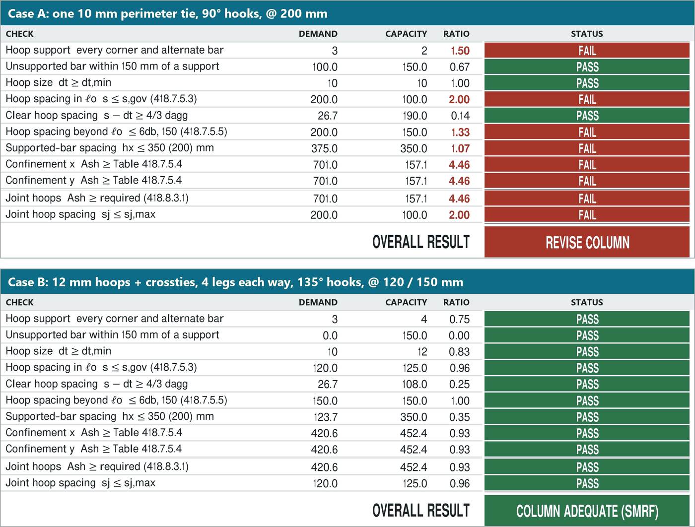
One 10 mm perimeter tie, 90-degree hooks, @ 200 mm from top to bottom.
Check (NSCP 2015)
Needed
Provided
Result
Confinement steel Ash (418.7.5.4)
701 mm²
157 mm²
FAIL, 4.5 times short
Tie spacing in the end zone (418.7.5.3)
100 mm max
200 mm
FAIL
Middle bars held by a hoop corner or crosstie (425.7.2.3)
every corner and alternate bar
corners only
FAIL
Joint ties
same as end zone
200 mm
FAIL
Overall: REVISE COLUMN.
Where does 701 mm² come from? NSCP 418.7.5.4 asks for the larger of two formulas. The governing one here is
Ash = 0.3 · s · bc · (f'c / fyt) · (Ag / Ach − 1)
With s = 200 mm, core width bc = 420 mm, f'c = 28, fyt = 420, Ag = 500² and Ach = 420²: Ash = 0.3 × 200 × 420 × (28/420) × (250,000/176,400 − 1) ≈ 701 mm². One 10 mm tie has two legs in each direction: 2 × 78.5 = 157 mm².
The spacing limit is the smallest of b/4 = 125 mm, 6 × 25 = 150 mm, and s₀ = 100 + (350 − hx)/3, which is capped at 100 mm when the tie legs are far apart (hx = 375 mm here). So the limit is 100 mm.
Case B: the corrected detail
12 mm hoops plus crossties, 4 legs each way, 135-degree hooks:
@ 120 mm in the end zones, ℓo = 500 mm from each beam face, and through the beam-column joint
@ 150 mm at mid-height
Check
Needed
Provided
Result
Confinement Ash at s = 120
421 mm²
452 mm² (4 × 113)
PASS
End-zone spacing
125 mm max
120 mm
PASS
Every corner and alternate bar held
yes
yes
PASS
Overall: COLUMN ADEQUATE (SMRF).
Figure 2. The sheet's own check summary for the two runs, case A ending in REVISE COLUMN and case B in COLUMN ADEQUATE (SMRF). Crops from the RC Column Section Designer SMRF; case labels and column headings added.
Notice what changed: more legs (crossties), slightly bigger bar, closer spacing only at the ends. The crossties also cut hx, the distance between legs, so the spacing limit rises from 100 to 125 mm. Good detailing makes the rules easier to meet.
Figure 3. Section of the 500 × 500 mm test column, drawn to scale. Case A: one 10 mm tie, 2 legs cross a cut through the column, Ash = 157 mm² against 701 mm² needed. Case B: 12 mm hoop plus crossties, 4 legs, Ash = 452 mm² against 421 mm² needed.
Why only the ends are tighter
The end zone length ℓo is the largest of the column depth, one-sixth of the clear height, and 450 mm (NSCP 418.7.5.1). That is where the bending is largest in an earthquake and where the cover spalls first. In the middle of the column the ties mainly stop bars from buckling and carry shear, so 418.7.5.5 allows wider spacing, here 6 × 25 = 150 mm.
Figure 4. Column elevation, roughly to scale. Case A: ties @ 200 mm everywhere, where the end zones and the joint need 100 mm or less and mid-height 150 mm or less. Case B: hoops @ 120 mm within ℓo = 500 mm at each end and through the joint, and @ 150 mm at mid-height.
What to check on site
Every hoop closed, with 135-degree hooks, and hook ends pointing into the core.
Hook extension at least 6db and 75 mm (for 10 mm bars that is 75 mm; for 12 mm, 75 mm).
Crossties on the middle bars as shown on the plans. Their 90-degree ends alternate from one tie to the next.
Closer spacing within ℓo at the top and bottom, and inside the beam-column joint. The joint ties are the ones most often left out, because they are hard to place once the beam bars are in.
Ties placed before the concrete, not "pushed in" later.
A note on blame
This is not about any one trade. Many crews were simply taught the 90-degree tie on non-seismic work, and it looks the same on a drawing at small scale. The fix is a clear hook detail on the plans and a quick check before the pour.
General information only. Follow the approved structural plans and the engineer of record.