A Balcony Slab Is a Cantilever: Thickness and Top Bars to NSCP 2015
On many two-storey houses, the balcony is formed and poured together with the second floor. It looks like a small extension of the floor slab. It is short, about 1.5 m (maikli lang), so a 100 mm slab with a few bars seems like enough.
But a balcony is not a small floor slab. It is a cantilever, and a cantilever follows different rules. Here is why, with a real check to NSCP 2015.
Why a cantilever is different
An inside slab rests on beams on both sides. A balcony is held on one side only, at the beam along the wall. That changes three things:
- The moment is bigger. For the same load and length, the moment of a cantilever is four times the mid-span moment of a simply supported slab (wℓ²/2 against wℓ²/8). It is largest at the root (ugat), at the face of the beam.
- The tension is at the top. The balcony bends down like a diving board, so the top surface stretches. The main (working) bars must be at the top. The bottom bars are still needed for shrinkage and temperature, and for the upward earthquake force covered below, so they are anchored into the support too.
- The tip sags more, and keeps sagging. A cantilever deflects much more than a slab of the same length supported on both sides, and the sag grows over the years as the concrete creeps.
That last point is why NSCP 2015 Table 407.3.1.1 asks for a much thicker cantilever. If you do not calculate the deflection, and the slab does not carry walls or other construction that large deflections could damage, a solid one-way slab must be at least:
| Support condition | Minimum thickness h |
|---|---|
| Simply supported | ℓ/20 |
| One end continuous | ℓ/24 |
| Both ends continuous | ℓ/28 |
| Cantilever | ℓ/10 |
These are for normal-weight concrete and fy = 420 MPa. For other grades they are multiplied by (0.4 + fy/700), which is 1.0 for fy = 420. For a cantilever, ℓ is the clear projection from the face of the support. If the balcony carries a CHB parapet or wall, the table is not enough: the deflection must be calculated (407.3.2).
So, unless deflection is calculated, a cantilever needs twice the minimum thickness of a simply supported slab of the same length. The sample that ships with our One-Way Slab Designer is a 2.80 m simply supported floor slab: its minimum is 2800/20 = 140 mm. A 1.50 m balcony, about half as long, needs 1500/10 = 150 mm.
The test case
I ran a 1.50 m balcony through our One-Way Slab Designer (NSCP 2015), set to Cantilever. Materials, cover, bars and finishes are the sheet's own sample (a two-storey residence); the live load is the balcony value:
- Clear projection ℓn = 1.50 m from the beam face, per 1 m strip
- f'c = 21 MPa, fy = 420 MPa, concrete 24 kN/m³
- Clear cover 20 mm (the sample's "not exposed to weather" value; see the open balcony note below), 10 mm bars
- Superimposed dead load 1.5 kPa (tiles and finishes)
- Live load 2.9 kPa, the NSCP 2015 Table 205-1 value for exterior balconies
- Factored gravity load wu = the larger of 1.4D and 1.2D + 1.6L (405.3.1); earthquake is discussed below
Only the thickness and the top bars change between the cases.
Case A: the thin slab
100 mm slab, top bars 10 mm @ 250 mm.
Self-weight is 24 × 0.100 = 2.40 kPa, so D = 2.40 + 1.5 = 3.90 kPa. On a 1 m strip, wu = 1.2 × 3.90 + 1.6 × 2.9 = 9.32 kN/m (1.4 × 3.90 = 5.46 is smaller). The moment at the root is
Mu− = wu ℓn² / 2 = 9.32 × 1.50² / 2 = 10.485, shown by the sheet as 10.49 kN·m/m
| Check (NSCP 2015) | Demand or limit | Provided | Result |
|---|---|---|---|
| Flexure, top bars | Mu− = 10.49 kN·m/m | φMn = 8.47 kN·m/m | FAIL, ratio 1.24 |
| Minimum thickness (Table 407.3.1.1) | h,min = 150 mm | h = 100 mm | CHECK DEFL. |
| Shear, no stirrups (422.5.5.1) | Vu = 13.98 kN/m | φVc = 43.82 kN/m | PASS (0.32) |
Overall: REVISE SLAB.
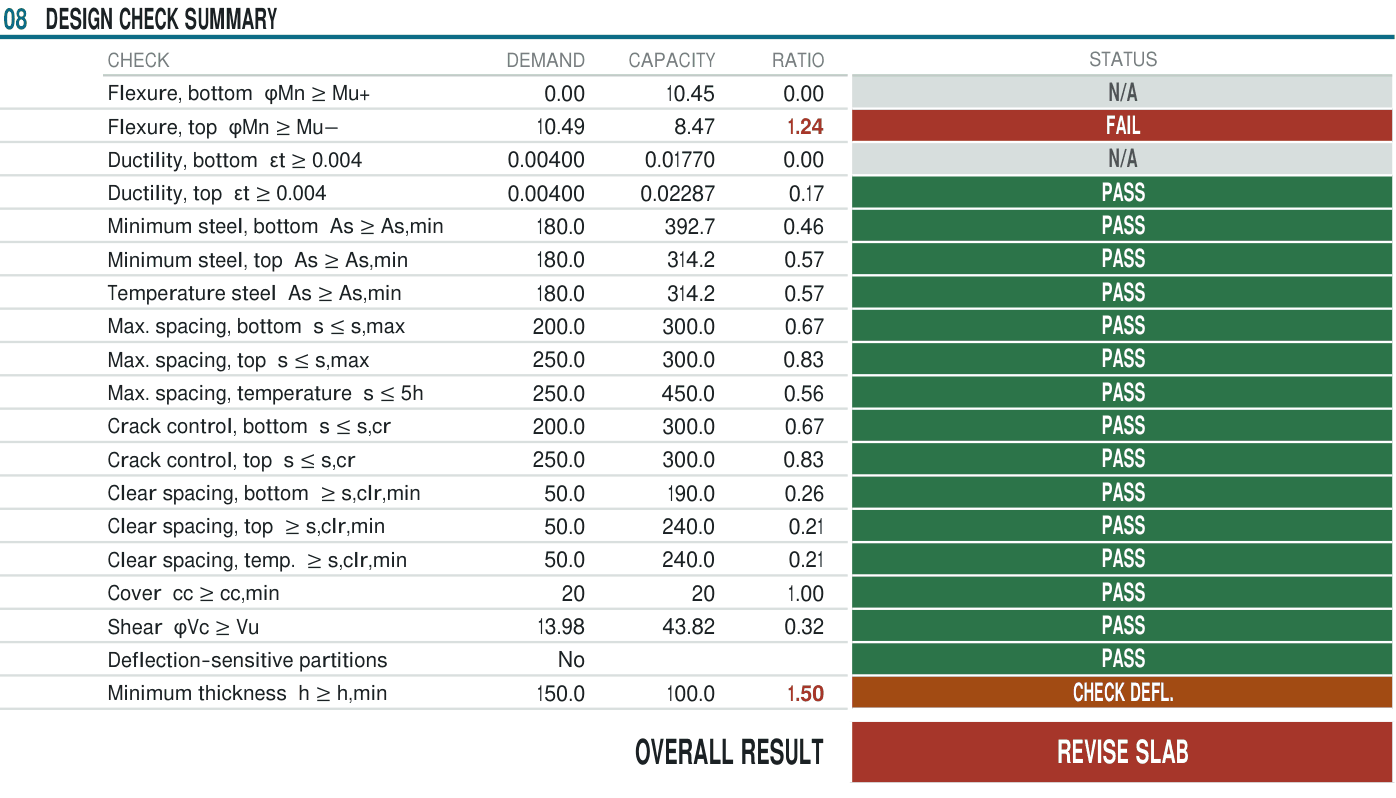
By hand: As = 1000 × 78.54 / 250 = 314.2 mm² per metre, at d = 100 − 20 − 10/2 = 75 mm. Then a = 314.2 × 420 / (0.85 × 21 × 1000) = 7.39 mm, and
φMn = 0.90 × 314.2 × 420 × (75 − 7.39/2) / 10⁶ = 8.47 kN·m/m
The section is tension-controlled (εt = 0.0229), so φ = 0.90. The factored moment is 1.24 times the design strength φMn, so this section does not meet the code.
Case B: more bars, same 100 mm
The usual reaction is to add steel: same 100 mm slab, top bars 10 mm @ 150 mm.
| Check | Demand or limit | Provided | Result |
|---|---|---|---|
| Flexure, top bars | Mu− = 10.49 kN·m/m | φMn = 13.62 kN·m/m | PASS (0.77) |
| Minimum thickness | h,min = 150 mm | h = 100 mm | CHECK DEFL. |
Overall: OK · CHECK DEFLECTION.
Strength is now fine: As = 523.6 mm²/m, a = 12.32 mm, φMn = 0.90 × 523.6 × 420 × (75 − 12.32/2) / 10⁶ = 13.62 kN·m/m. But the slab is still 50 mm thinner than ℓ/10, and more steel helps the strength but only a little with stiffness. It does not satisfy ℓ/10. You must either calculate the deflection, including the long-term part (407.3.2), or make the slab thicker. Thickness is by far the more effective fix.
Case C: the fix, 150 mm
h = ℓ/10 = 1500/10 = 150 mm, top bars 10 mm @ 200 mm (the bar spacing of the sheet's sample).
The thicker slab is heavier: self-weight 24 × 0.150 = 3.60 kPa, D = 5.10 kPa, wu = 1.2 × 5.10 + 1.6 × 2.9 = 10.76 kN/m. The moment goes up by about 15%:
Mu− = 10.76 × 1.50² / 2 = 12.105, shown as 12.11 kN·m/m
But d grows by two thirds, from 75 to 150 − 20 − 5 = 125 mm:
As = 1000 × 78.54 / 200 = 392.7 mm²/m; a = 392.7 × 420 / (0.85 × 21 × 1000) = 9.24 mm
φMn = 0.90 × 392.7 × 420 × (125 − 9.24/2) / 10⁶ = 17.87 kN·m/m
| Check | Demand or limit | Provided | Result |
|---|---|---|---|
| Flexure, top bars | Mu− = 12.11 kN·m/m | φMn = 17.87 kN·m/m | PASS (0.68) |
| Minimum thickness | h,min = 150 mm | h = 150 mm | PASS (1.00) |
| Shear, no stirrups | Vu = 16.14 kN/m | φVc = 73.03 kN/m | PASS (0.22) |
Overall: SLAB ADEQUATE.
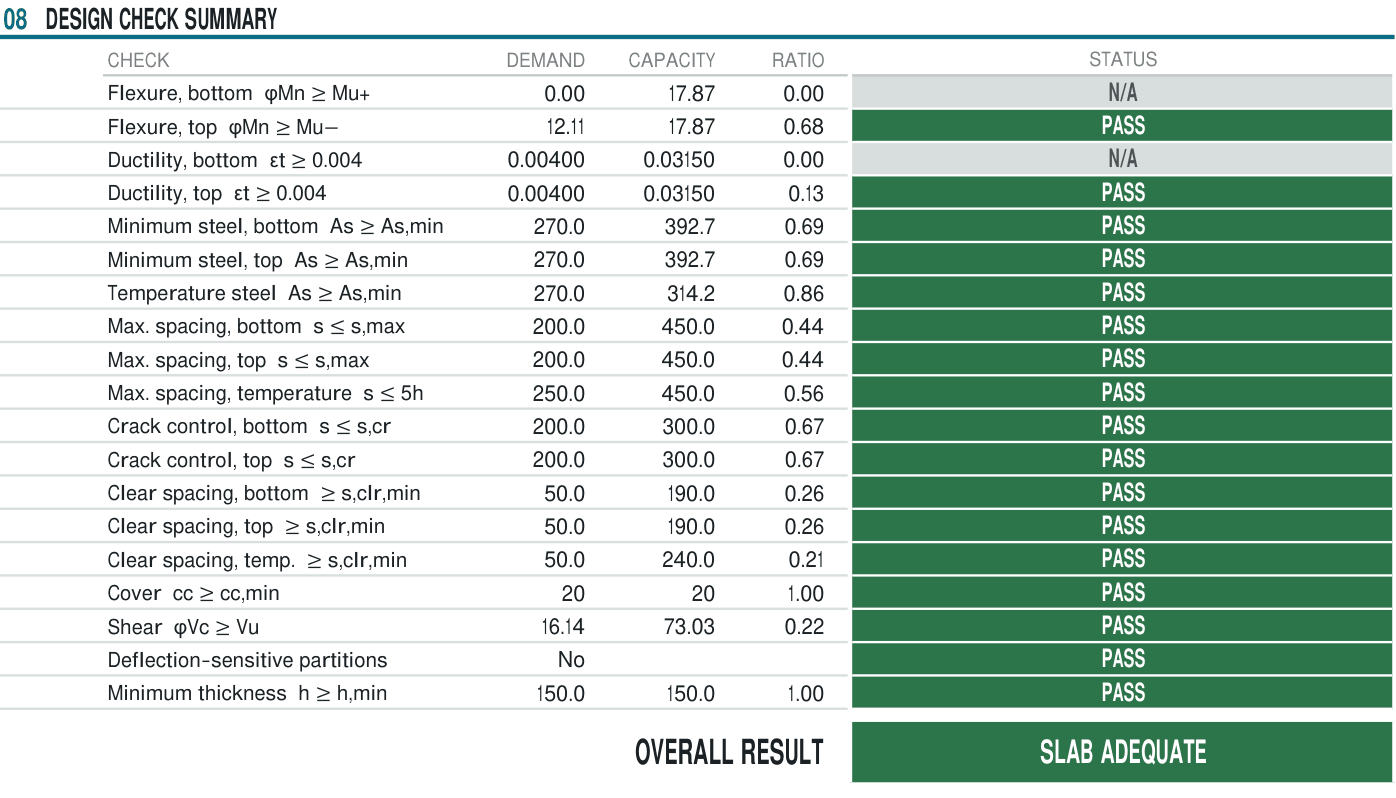
Notice that case C has fewer bars than case B (10 mm @ 200 instead of @ 150) and passes everything. Thickness did what extra steel could not.
The lesson
For a balcony, start with a thickness of at least ℓ/10, then size the bars. Adding steel to a thin cantilever fixes the strength on paper, but does not by itself deal with the sag. And because the tension is at the top, d is measured to the top bars: if they are stepped down during the pour, strength is lost.
Four things our test case does not cover:
- A wall or heavy railing at the tip. The case has uniform loads only. A CHB parapet at the edge acts on the full 1.5 m lever arm. Work out its moment by hand and use the sheet's "Direct input" method. It also makes the deflection check necessary, as noted above.
- An open balcony. If rain reaches the slab, the cover for these bars is 40 mm, not 20 mm (Table 420.6.1.3.1). Treat most balconies here as exposed, unless the engineer decides otherwise. Then d = 150 − 40 − 5 = 105 mm. My hand check, not a sheet run: φMn = 0.90 × 392.7 × 420 × (105 − 9.24/2) / 10⁶ = 14.90 kN·m/m, still above 12.11 (ratio 0.81). Run it on the sheet with the exposed setting.
- Where the moment goes. The top bars must continue over the beam into the inside slab far enough to develop (see Development Length and Lap Splices). With no slab behind, the beam must carry the moment by twisting (torsion). The sheet does not check anchorage; show it on the plans.
- Earthquake. NSCP 2015 Section 208 requires horizontal cantilevers in Zone 4, which covers most of the Philippines, to be designed for a net upward force. The engineer of record also checks the root for this reversed moment and the bottom-bar anchorage.
What to check on site
- Thickness at least ℓ/10 of the clear projection, unless the engineer has calculated the deflection. For 1.5 m, that is 150 mm.
- Main bars on top, as the outer layer, with the temperature bars under them.
- Firm supports under the top bars, so they keep their height when people walk on them. Check again just before concreting.
- Top bars run back over the beam into the inside slab, as long as the plans show. Do not cut them at the beam line.
- No construction joint at the root. Pour the balcony together with the inside slab, and check the closed stirrups of the supporting beam.
- Shores stay under the balcony until the engineer says they can come out. Do not stack hollow blocks or cement bags on it, during or after shoring.
- Later, a crack along the wall line (or hollow-sounding tiles there), a tip that visibly drops, or a railing that leans out are signs to call the engineer. Water running back toward the house is a drainage problem; fix it too, since standing water rusts the top bars faster.
This is not about any one trade. The fix is a clear balcony section on the plans and a quick check before the pour.
General information only. Follow the approved structural plans and the engineer of record.