Why a C Purlin Should Not Be Laid Flat (and Why Sag Rods Still Matter)
On small steel roofs I sometimes see C purlins laid flat (nakahiga): the web on top, along the roof, and both flanges pointing down onto the truss top chord. Perhaps the flat web looks like a wide seat for the roof sheet.
But a C purlin is strong in one direction only. Laid flat, it carries the roof with its weak side. Here are the numbers for a sample roof checked to NSCP 2015.
A C section has a strong axis and a weak axis
Think of a plank: on its edge it hardly bends, laid flat it sags. A C purlin is the same.
For the C150×50×14×2.0 in this example:
- Bending strength about the strong axis: φMnx = 4.173 kN·m
- About the weak axis: φMny = 0.917 kN·m with the web side in compression (0.922 kN·m with the flange tips in compression), less than a quarter of the strong-axis strength
- Stiffness: Ix / Iy = 1,733,263 / 161,176 = 10.75, so it bends almost 11 times more on the weak axis
On a sloping roof, the load on each purlin splits in two:
- wn, normal to the roof: the big part, including all of the wind.
- ws, along the slope: the small part.
The correct way is upright, with the web square to the roof (nakahilig), usually bolted to an angle cleat on the top chord as detailed. Then wn goes on the strong axis and only ws on the weak axis. Laid flat, it is the reverse.
The test roof
I used the shipped sample of our Roof Framing Designer (NSCP 2015):
- One-storey shop in Metro Manila, 12 × 24 m, trusses at 4.0 m (the purlin span)
- Roof slope 1 : 3 (18.43°), purlins at 0.79 m along the slope, 0.40 mm roof sheet
- C150×50×14×2.0, ASTM A1011 SS Grade 33 (Fy = 230 MPa), on the main lines. The sample uses a heavier C200×75×16×2.5 on the edge lines at the eave and ridge strips (P0, P1, P8, P9).
- Dead load: roof sheet and purlin only (no ceiling hung from the purlins)
- Wind 260 km/h, Exposure C
The governing gravity combination is 1.2D + 1.6Lr + 0.5W (NSCP Eq. 203-3), with D = 0.0799 kN/m, Lr = 0.75 kPa (Table 205-3) × 0.75 m on plan = 0.5625 kN/m, and the wind pressure W⁺ = 0.981 kN/m:
vertical part = 1.2 × 0.0799 + 1.6 × 0.5625 = 0.996 kN/m
ws = 0.996 × sin 18.43° = 0.315 kN/m
wn = 0.996 × cos 18.43° + 0.5 × 0.981 = 1.435 kN/m
Uplift (0.9D + 1.0W, Eq. 203-6) uses the suction instead: W⁻ = 2.360 kPa × 0.7906 m = 1.866 kN/m, so w_up = 1.866 − 0.9 × 0.0799 × cos 18.43° = 1.797 kN/m and Mu = 1.797 × 4.0² / 8 = 3.595 kN·m.
One honest note. The sheet has no laid-flat input, so Case A is my hand calculation with the sheet's loads and section values. Cases B and C are the sheet's own results for the design line, a C150 main line.
Case A: laid flat
With M = wL²/8 over the 4.0 m span:
| Check | Demand | Capacity | Ratio | Result |
|---|---|---|---|---|
| Weak axis, Muy = 1.435 × 4.0² / 8 | 2.87 kN·m | 0.917 kN·m | 3.13 | FAIL |
| Strong axis, Mux = 0.315 × 4.0² / 8 | 0.63 kN·m | 4.173 kN·m | 0.15 | see combined |
| Combined bending (553.5) | 3.28 | FAIL | ||
| Wind uplift, weak axis (section only) | 3.595 kN·m | 0.922 kN·m | 3.90 | FAIL |
| Sag under Lr | 54.4 mm | 26.7 mm (L/150) | 2.04 | FAIL |
The purlin is more than three times over. A cross-check on the gross section gives 3.01, also a FAIL. The 3.28 is higher because the wide flat web buckles locally.
The sag is the upright value times the stiffness ratio. Under D + Lr, for information, it is 5.77 mm upright and about 62 mm laid flat (5.77 × 10.75). Under workers and materials, the roof sheet goes visibly wavy between the trusses. The limits L/120 and L/150 are from IBC 2009 Table 1604.3, which the sheet uses; NSCP 2015 prints no purlin deflection limit.
If your existing roof already has laid-flat purlins, please do not panic, and do not walk on them. These ratios use the full design loads, including typhoon wind; a roof can stand for years and still lack the code strength. Have a licensed civil or structural engineer, ideally the engineer of record, assess it before typhoon season.
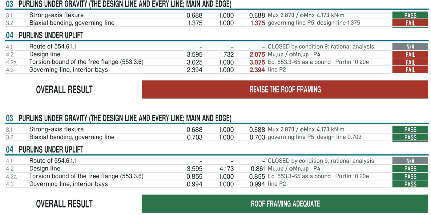
Case B: upright, but no sag rods
Upright, strong-axis bending is 2.870 / 4.173 = 0.688. But with no sag rods, the sheet still says no:
| Check (Design Check Summary) | Ratio | Result |
|---|---|---|
| Strong-axis bending only | 0.688 | PASS |
| Combined bending, gravity | 1.375 | FAIL |
| Wind uplift, design line | 2.075 | FAIL |
| Torsion bound of the free flange | 3.025 | FAIL |
Overall: REVISE THE ROOF FRAMING.
Why? The small slope load ws still bends the weak axis over the full 4.0 m: 0.630 / 0.917 = 0.687, and 0.688 + 0.687 = 1.375. In wind uplift the bottom flange is in compression. With no rods, the sheet conservatively treats it as unbraced over 4.0 m, so the lateral-torsional strength drops to 1.732 kN·m. The torsion row is the sheet's conservative bound for the twisting of that free flange.
Check only strong-axis bending and you see a pass. That is the trap.
Case C: upright, with sag rods
This is the sheet's own sample: 12 mm sag rods at the third points (every 1.33 m), a line near each flange, plus a ridge tie between the two ridge purlins.
| Check | Ratio | Result |
|---|---|---|
| Combined bending, gravity | 0.703 | PASS |
| Wind uplift, design line (3.595 / 4.173) | 0.861 | PASS |
| Torsion bound of the free flange | 0.855 | PASS |
| Worst purlin line, interior bays | 0.994 | PASS |
Overall: ROOF FRAMING ADEQUATE (with the sample's C200 edge lines).
The governing formula is the combined-bending interaction of NSCP 553.5, with no axial load:
Mux / φMnx + Muy / φMny ≤ 1.0
Hand check at mid-span. The rods turn the weak axis into three spans of l = 1.333 m, so Muy = 0.025 × 0.315 × 1.333² = 0.014 kN·m, on the tip side (0.922):
2.870 / 4.173 + 0.014 / 0.922 = 0.688 + 0.015 = 0.703, OK
In uplift, the bottom rods brace the free flange every 1.33 m. Lateral-torsional buckling rises to 4.69 kN·m, so the distortional strength, 4.173 kN·m, governs: 3.595 / 4.173 = 0.861.
The lesson: orientation first, then sag rods
Same main purlin, same roof, same loads. Laid flat: 3.28 in gravity and 3.90 in uplift (section strength only). Upright with no rods: 1.375 and 2.075. Upright with rods: 0.703 and 0.861.
Two more runs on the same sheet:
- Rods near the top flange only. Gravity passed at 0.703, but uplift stayed at 2.075, FAIL. A top line does not brace the bottom flange.
- A bigger purlin instead of rods. A C200×75×16×2.5 has about 73% more steel (903.2 against 522.8 mm²). Without rods it passed gravity and the main uplift check, but still failed the sheet's conservative free-flange torsion check (1.634).
Here the rods solved it with far less steel.
What to check on site
- Purlins upright as detailed, seated and bolted on the cleat. Never laid flat unless the engineer of record designed it that way.
- Sag rods: the number of lines and their positions exactly as the plans show. In this sample, two lines at the third points (common practice for a 4.0 m span).
- If the plans show rods near both flanges, check both lines. The bottom line braces the free flange in uplift.
- The ridge tie and the ties at the ends of the rod lines, as detailed.
- Rods straight and snug, nuts on both sides, every cleat fully bolted and welded. If anything differs from the plans, or there is no purlin detail, ask the engineer of record.
This is not about any one trade. A laid-flat purlin looks tidy, and a purlin without rods looks finished. The fix is a clear purlin detail on the plans and a quick look before the roofing goes on.
General information only. Follow the approved structural plans and the engineer of record.