Building Separation From the Property Line: How Much Gap Does NSCP 2015 Require?
On narrow lots in our cities, a new building is often built tight against the boundary. Sometimes the new column is cast right against the neighbour's wall, wall to wall (pader sa pader). Sometimes a gap of about two inches, 50 mm, is left, like an expansion joint, and filled with styrofoam.
Both look fine on the day the building is finished. But a building in a strong earthquake needs room. Here is how much, with a check to NSCP 2015.
What happens in the gap
In an earthquake every building sways, and the top sways the most. The neighbour's house sways too, but at its own rhythm, because its height and stiffness are different. If the gap is smaller than the sway, the two buildings hit each other. Engineers call this pounding.
Pounding is a short, hard blow. It can crush the concrete where the two buildings meet. When the floors are at different heights, the slab of one building can strike a column of the other at mid-height, a place never designed for it.
The analysis number is not the full movement
When we analyse a building for earthquake, in ETABS or any other program, the seismic forces are reduced by the factor R. This is allowed because a well-detailed frame yields and absorbs energy. So the displacement the program reports, ΔS, belongs to these reduced design forces.
In the design earthquake the building can move much more. NSCP 2015 estimates this as the maximum inelastic response displacement:
ΔM = 0.7 · R · ΔS (Section 208.6.4.2, Equation 208-21)
For a special reinforced concrete moment frame, R = 8.5 (Table 208-11A). So 0.7 × 8.5 = 5.95. For this system the code estimate is almost six times what the analysis shows. Other systems have other R values.
ΔS must include torsion (208.6.4.1). Take the displacement at the edge of the plan, not only at the centre of mass.
The rule at the property line
NSCP 2015 Section 208.7.2.9 requires all structures to be separated from adjoining structures by enough to allow for ΔM. When the neighbour is on another lot, and the property line is not a street or other public way, your building must be set back from the property line by at least its own ΔM.
The idea is fair: each building keeps its own sway inside its own lot. You cannot count on the neighbour's setback, and the neighbour cannot count on yours.
When two buildings stand on the same property, the gap is ΔMT = √(ΔM1² + ΔM2²) (Equation 208-23). Both buildings sway, but with different periods they rarely reach their largest movement toward each other at the same instant. So the code does not simply add them. Smaller separations are allowed only when justified by a rational analysis based on the maximum expected ground motion.
The building-permit setbacks for light, air and fire are separate rules. Where both apply, the larger setback governs. Permission to build up to the line does not remove the seismic gap.
The test case
I ran the check in our Storey Drift & P-Delta Checker (NSCP 2015). It is a sample case, not a real project:
- 3-storey RC building beside a 2-storey house on the next lot
- Special RC moment frame, R = 8.5, Seismic Zone 4
- Storey heights 3.5 + 3.0 + 3.0 m, roof at 9.5 m
- Assumed analysis results, typed into the sheet (not from a real model): periods 0.55 s (X) and 0.60 s (Y)
- Elastic roof displacement: 19.5 mm (X) and 21.0 mm (Y) at the centre of mass; at the edge of the plan, with torsion, 21.06 mm and 22.26 mm
First, the drift. The largest storey drift is 1.45% (X) and 1.55% (Y) of the storey height, at the ground storey, against a limit of 2.5% (208.6.5.1, for T under 0.7 s). The P-Delta ratio θ is 0.022 and 0.024, below 0.10, so P-Delta effects need not be added (208.6.3). The frame passes drift.
The sheet then works out ΔM at every level:
| Level (height above the base) | ΔM, X | ΔM, Y |
|---|---|---|
| Roof deck (9.5 m) | 125.3 mm | 132.4 mm |
| 3rd floor (6.5 m) | 93.8 mm | 99.7 mm |
| 2nd floor (3.5 m) | 50.8 mm | 54.2 mm |
By the code's estimate the roof can move about 13 cm. Even the 2nd floor comes out above 50 mm.
Case A: the 2-inch gap
Gap 50 mm in both directions, the "2 inches" of the site.
| Check (208.7.2.9) | Needed | Provided | Ratio | Result |
|---|---|---|---|---|
| Separation, X | 125.3 mm | 50 mm | 2.51 | FAIL |
| Separation, Y | 132.4 mm | 50 mm | 2.65 | FAIL |
Overall result of the sheet: REVISE — SEE FAILS.

The gap is less than half of what the code asks for. By the code's estimate, the roof and the 3rd floor could move well past the property line in the design earthquake, and the 2nd floor just past it.
And wall to wall, with zero gap? Then there is no room at all, and the building does not meet 208.7.2.9 at any level. (Our sheet shows CHECK for a 0 mm gap, so it is never passed by mistake.)
Case B: a gap sized to ΔM
Gap 150 mm in both directions. That is the larger ΔM, 132.4 mm, rounded up to the next 25 mm.
| Check (208.7.2.9) | Needed | Provided | Ratio | Result |
|---|---|---|---|---|
| Separation, X | 125.3 mm | 150 mm | 0.84 | PASS |
| Separation, Y | 132.4 mm | 150 mm | 0.88 | PASS |
Overall result of the sheet: DRIFT OK.
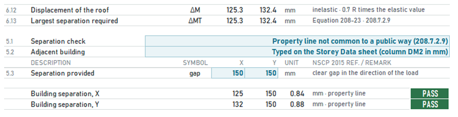
Hand check of the Y direction, which governs:
ΔM = 0.7 × 8.5 × 22.26 = 5.95 × 22.26 = 132.4 mm ≤ 150 mm. Ratio 132.4 / 150 = 0.88.
The lesson
The number in the analysis output is not the full movement. Multiply it by 0.7 R, take it at the edge of the plan, and use the largest ΔM of your own building, normally at the roof, whatever the height next door. The neighbour may build higher later. Here that turned 22.26 mm into 132.4 mm.
Notice too that this frame passed every drift check. A building can pass drift and still be too close to the boundary. The two checks answer different questions.
And 150 mm is right for this building only. In a four-storey sample on the same sheet (roof at 12.5 m), the roof ΔM came out 192.4 mm, so the gap was set at 200 mm. Taller or more flexible buildings need more room.
What to check before and during construction
- Ask for the ΔM at every level, in both directions, from the edge displacements times 0.7 R. The largest, usually at the roof, sets the setback.
- Make sure the model used cracked section stiffness (208.6.2). An uncracked model shows smaller displacements and too small a gap.
- Show the setback as a clear dimension on the plans and check it at layout, before the footings are dug. Measure it to the outermost face at every level, including plaster, cladding, balconies, cantilevered slabs, eaves and gutters, not to the gridline. Have a geodetic engineer confirm the lot corners first. Once the columns are cast, the gap cannot be widened.
- Keep the gap clear for the full height: no slab, beam, canopy, gutter or parapet crossing it, and no hollow blocks, mortar or forms left inside.
- Fill the joint only with soft, flexible material. Fix any flashing or cover on your side only, so it can slide or fold through the full ΔM, about 130 mm here, without locking against the neighbour's wall.
- Adding a storey later? ΔM changes. Have the gap checked again.
- Already built close to the line? Do not cut or chip anything yourself. Ask a structural engineer, ideally the engineer of record, to check the gap against ΔM.
This is not about any one trade. The gap is decided on paper, long before the first block is laid.
General information only. The seismic gap is part of the structural design: follow the approved plans and the engineer of record.